То тва по просто и от бобена манджа
 Давай го насам
Ако искаш купи си чарковете или ела да се уговорим кое да си купиш останалото щи го сглобим.
В сервиза на "Бергон компютри" съм, Хотел България до касата на Бергон Интернет-а.
| Бергон интернет и телевизия http://109.104.192.11/ |
|
| Help. Осъществяване на схема! http://109.104.192.11/viewtopic.php?f=38&t=52068 |
Страница 1 от 1 |
| Автор: | -==WestBam==- [ 10 Май 2010 19:59 ] |
| Заглавие: | Help. Осъществяване на схема! |
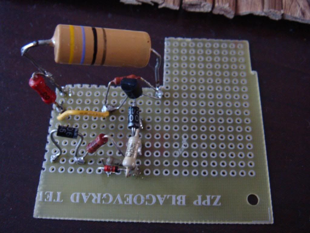
Има ли някой, Който може да ми осъществи една мижава схема, която лъже така нареченият "EGR Клапан" за колата. Намерих схема, снимки и обяснения, но не разбирам на схеми, и ми трябва някой който да ми каже кое как да свържа. Има точно 10 елемента + едно кабелче в тази схема. Ако някой прояви интерес да ми помогне, ще му пратя снимките и схемата по скайп или ще ги постна тук във форума! |
|
| Автор: | -==WestBam==- [ 10 Май 2010 20:02 ] |
| Заглавие: | Re: Help. Осъществяване на схема! |
Ето ги и снимките ---> http://i225.photobucket.com/albums/dd11 ... C00645.jpg http://i225.photobucket.com/albums/dd11 ... C00001.jpg Ето я и схемата --> http://www.z22se.co.uk/forum/userpix/13 ... on_2_1.jpg А това е обяснението, на английски е, но не мисля че ще представлява проблем! Checking through the Haynes manual, the connector for the Z12XE is different, which isn't a suprise, although the connections you list for the Z16XE seem to match the Haynes manual for the Z14XE. So from my understanding of the diagram: * Pin A is the pin from ECU that drives the valve open/shut (inverse of z22se pin E) * Pin B is ground (assuming brown = ground) (pin A on z22se) * Pin C is the EGR output (pin B on z22se) * Pin D is 5v (seems to be connected to +ve on camshaft sensor) (pin D on z22se) * Pin E is 12v (not connected on z22se) * The relay is used to drive the input to the top left diode to 0v when A is 12v and to 12v when A is 0v However, I'm a bit confused by what the final voltage at C would be and why... My understanding of electronics is almost 20 years rusty now, but this is what I think is happening: * The Zener seems to be making the voltage at C a maximum of 4.7v, except I'm not sure what the 1k5 resistor is for. * After the diode on the top right, you have 4.3v going through the 3k3 and 11.3v or 0v going through the 4k7. * Is the resistor in parallel to the Zener to reduce the voltage? Does that mean that the voltage at C is 3300/4800 * 4.3 = 2.95v or 4700/6200 * 11.3v = 8.56v (limited to 4.7v) depending on the input at pin A? (I'm not really sure how diode and resister in parallel work) * What's the point of the 5v through the resistor to generate 2.95v as the "low" value - is it just to protect the bottom diode? Otherwise when the relay was providing 0, presuming that would be fine too? * This variable voltage is used to simulate different readings when the valve is open/shut, presumably when the ECU is making sure the EGR is connected correctly. * Am I completely off track? I guess after that, I'm on my own, but it looks like for the Z12XE, I can map A-1, B-2, C-4, D-3, E-5 on my EGR connector. I'm not sure how I determine if I need to use the relay, although I can always try both ways I guess... |
|
| Автор: | Falco [ 18 Май 2010 01:47 ] |
| Заглавие: | Re: Help. Осъществяване на схема! |
То тва по просто и от бобена манджа Давай го насам Ако искаш купи си чарковете или ела да се уговорим кое да си купиш останалото щи го сглобим. В сервиза на "Бергон компютри" съм, Хотел България до касата на Бергон Интернет-а. |
|
| Автор: | The Transporter [ 18 Май 2010 17:28 ] |
| Заглавие: | Re: Help. Осъществяване на схема! |
нетие нужна схема, това си е чисто и просто един клапан управляван от вакуум който преспокойно можеш да го затапиш с една ламарина и да не ти вкарва изгорелите газове в всмукателния колктор. |
|
| Автор: | -==WestBam==- [ 05 Сеп 2010 20:05 ] |
| Заглавие: | Re: Help. Осъществяване на схема! |
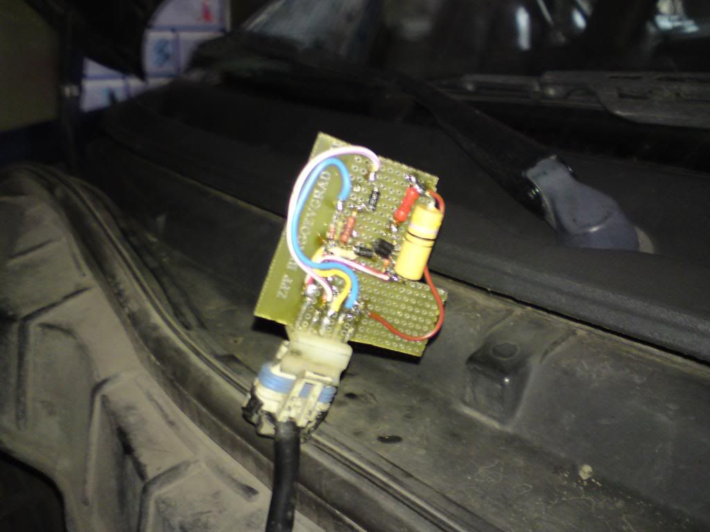
Електронен е простия клапан, който прецаква цялата работа. По въпроса аз го оправих той просто бил загорял отвътре, изчистих го и се оправи! Ако на някой му е нужна схемата, тя работи, слагали сме я на опел тигра пак екотек и си работеше чудесно, но компютъра пак започна да се обърква след седмица 2...
|
|
| Страница 1 от 1 | Часовете са според зоната UTC + 2 часа [ DST ] |
| Powered by phpBB® Forum Software © phpBB Group http://www.phpbb.com/ |
|